
TB 11-5830-263-20-14
d . Mechanic's FFCS Cabling Installation (Fig. 4-9)
1. Secure connector P2 of the Highway Cable Assembly (1), routed to the
Commander's FFCS (Figure 4-6), to the right side Station connector of
the Mechanic's FFCS (3).
2. Secure connector P2 of the Highway Cable Assembly (1), routed to the
MCS (Figure 4-5), to the left side Station connector of the Mechanic's
FFCS (3).
3 . Loosely secure cable routing using tiedown straps (7) supplied with kit.
Locate tiedown straps approximately as shown in Figure 4-9.
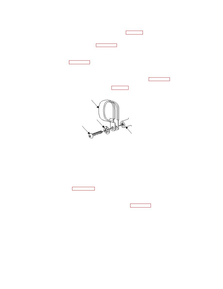
e. Cable Loop Clamp Installation (Fig. 4-8)
1
3
2
(WELDED
BOSS)
1 . Clamp, Loop Type (MS21333-107)
2 . Screw, Machine-Pan Head, (#10-32UNF-2A), MS35207-265
3. Washer, Lock, Flat-Internal Tooth, (#10) MS35333-39
1. Refer to Figures 4-5, 4-6, and 4-7 for the appropriate locations for
installing the cable loop clamps.
2. Using a cross-tipped screwdriver, install the cable loop clamps (1) and
attaching hardware (2) (3) as shown in Figure 4-8 at the locations
shown in the Figures referenced in Step 1.

