
TM 11-5830-263-10
FFCS: CONTROLS AND INDICATORS - Continued
Table 2-8. O/R INTERCOM Switch Setting of FFCS
FFCS
FFCS
WORK
MONITOR
SWITCH
SWITCH
TYPE OF COMMUNICATION
Any setting
Any setting
In this setting, signals are received based on
MCS programming from the selected radio(s),
however the transmitted intercom override
signal is received by all other crew members.
When the ACCENT switch on the MCS is set
to ON, this override intercom signal is
emphasized above the level of any radio
signals being received.
2.4.
MOS: CONTROLS AND INDICATORS.
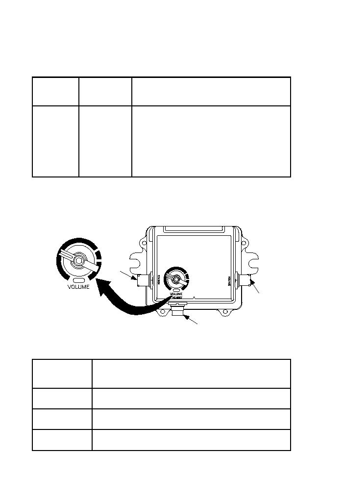
2.4.1.
CONNECTORS
MONITOR ONLY (CREW) STATION
MONITOR ONLY
(CREW) STATION
J3
J1
J2
Figure 2-14. VOLUME Control of MOS
Table 2-9. MOS Connectors and Function
CONNECTOR/
TERMINAL
FUNCTION
REF DES
STATION/J1
Highway cable connector; interface between all units in the
system
HEADSET/J2
Cable connector which provides interface to a headset or
loudspeaker
STATION/J3
Highway cable connector; interface between all units in the
system
2 - 16

