Home
Download PDF
Order CD-ROM
Order in Print
Figure 5-10. VSWR Adjustment Troubleshooting Test Setup
Section IV. Subject General . . . . . . . . . . . . . . . . . . . . . . . . . . . . . .. . Operational Check . . . . . . . . . . . . . . . . . . . . . Repair Instructions . . . . . . . . . . . . . . . . . . . . Disassembly for Troubleshooting . . . . . . . . Replacement of Power Amplifier Cover . . . Replacement of Decoder Control (6A2) . . Replacement of Power Amplifier Heat Sink MAINTENANCE PROCEDURES
TM-11-5820-890-30-4 Ground ICOM Radio Sets: Receiver-Transmitter Radio RT-1523(C)/U (NSN 5895-01-234-8093) Manual
Page Navigation
584
585
586
587
588
589
590
591
592
593
594
FIGURE 5-10.
TM 11-5820-890-30-4
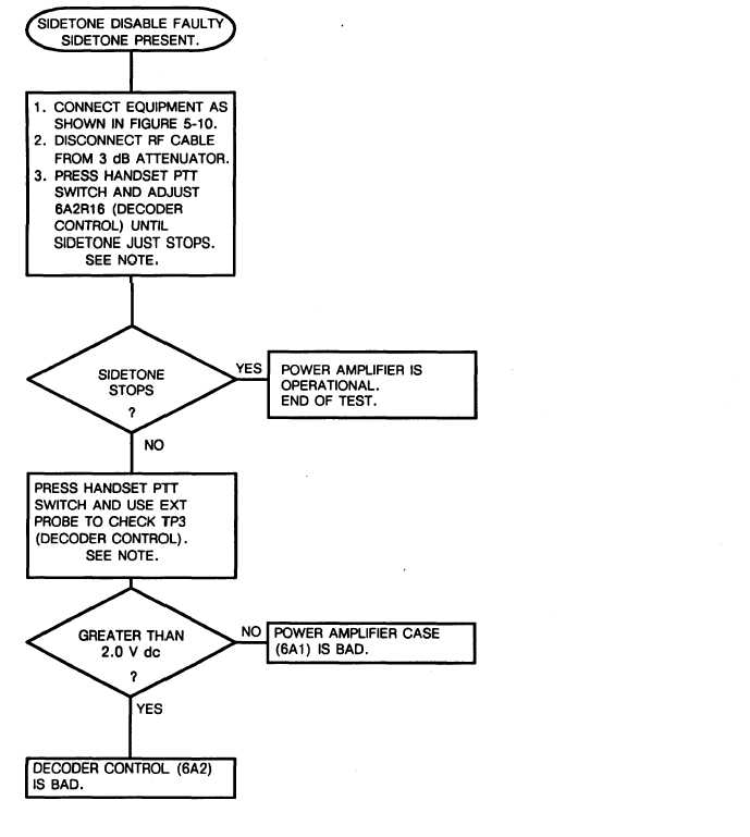
5-14. TROUBLESHOOTING
FLOWCHARTS
.
Continued
Chart 7
Troubleshooting 5:1 VSWR Adjustment Circuit
(Sheet 1 of 1)
NOTE:
See figure 5-5 for the location
of test points and referenced
components.
5-33