TM 11-5820-890-30-4
6-16. EXPLANATION OF SYMBOLS AND NOTES.
SYMBOL
EXPLANATION
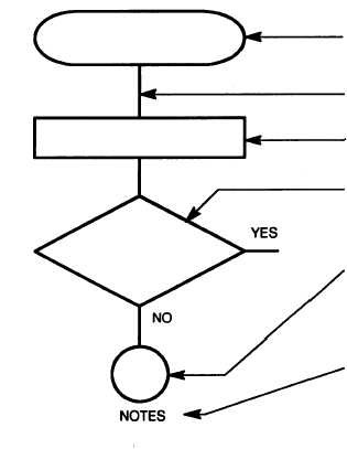
Test Procedure Start: (Rectangle with rounded sides)
Indicates start of the test procedure and contains a brief
description of the symptom of trouble.
Test Procedure Flow Line: (Heavy line) Indicates direction
of the procedure flow.
Test Procedure Instruction: (Rectangle) Provides test
setup or instructions
Decision: (Diamond)
made (YES or NO)
previous test. Path
(YES or NO).
for doing a specific test.
Indicates that a decision must be
in answer to question about the
taken depends on the answer
Connector: (Circle) Directs user to an entry point of
another chart. Contains an entry number that is the same
as entry number of other chart and a sheet number
(Sh. No.) that indicates the number of follow-on pages.
Notes Column: Presents additional information, such
as: more specific instructions about how to do a test,
cautions and warnings that must be observed when doing
a test, and additional information about what to do after
doing a test. Also provides reference to appropriate
circuit diagrams.
6-17. TROUBLESHOOTING FLOWCHARTS.
The following charts are included:
Chart
Symptom
1
No display.
2
All display segments stay lit.
3
Self-test “F2” display.
4
Incorrect radio XMT output.
5
CONTROL M lit, all others blank.
6
Incorrect display in RF.
7
Incorrect display in FCTN: MODE or VAR.
8
Incorrect display in CONTROL.
9
“Er” not displayed.
10
“Fr” not displayed and/or CONTROL M not lit.
11
CM OUT incorrect.
12
Incorrect display after test cycle.
13
“Ud” not displayed or incorrect indicators.
14
Power supply output low.
15
Incorrect display in FCTN: CHAN or COMSEC.
6-18


