TM 11-5820-890-30-4
12-1. INTRODUCTION. Continued
The front panel/chassis includes:
The front panel with its switches, controls, connectors, and displays.
The module interconnections.
Frame for physical support of the modules.
System and battery connectors.
it is described in paragraph 12-6.
A description of the types of signals present in the RCU is included in paragraph 12-7.
Paragraphs 12-8 through 12-15 provide functional descriptions of the RCU in different modes of operation.
12-2. CONTROL SECTION.
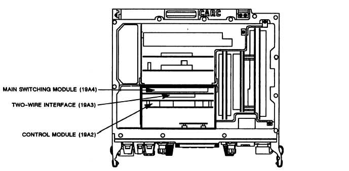
The control section consists of three modules. They are:
Electronic Component Assembly - Control 19A2 (control module).
Circuit Card Assembly - Two-Wire Interface 19A3 (two-wire interface),
Circuit Card Assembly - Switching 19A4 (main switching module).
The module locations are shown in figure 12-3.
Figure 12-3. Control Section Module Locations
12-4


