TM 11-5820-890-10-1
5, 6. E1B/E2B and E1A/E2A: Wireline adapter terminals for top (RT B) and lower
7.
8.
9.
10.
(RT B) . Used to connect Control, Receiver-Transmitter C-11561 (C)/U.
AUD/DATA B J2: Connects to headset or handset for RT in position B.
AUD/DATA A J3: Connects to headset or handset for RT in position A.
DATA B J4: Connects to AUD/DATA connector on RT in position B. Routes
audio from/to intercom; provides audio to AUD/DATA B J2.
DATA A J5: Connects to AUD/DATA connector on RT in position A. Routes
audio from/to intercom: provides audio to AUD/DATA A J3.
SPKR J6: Connects to loudspeaker for monitoring RT in position A or B.
Indicator lamp and lens: Shows when power is on. Lights when CB1 is set
to ON. On the AM-7239A/VRC version, when CB1 is first turned on, the indica-
tor light will blink for about three seconds then stay lit. If the indicator light
continues to blink, the mounting adapter is bad and Unit Maintenance must
be notified. Lens adjusts brightness: turn it left (counterclockwise) to make
lamp brighter; turn it right (clockwise) to make it dimmer. Do not turn past
full bright. Full dim to full bright is approximately one quarter turn. Turn full
clockwise when you are wearing night-vision goggles.
Switch CB1: Turns power on and off to mounting adapter and to mounting
base of power amplifier (in LR/LR system).
Mounting base: Provides power to mounting adapter. Holds mounting adapt-
er. Bolted in vehicle.
11.
12.
Mounting adapter: Provides interface and support to RT and power amplifier
(in long-range radios).
Connector J1: Mates with connector on power amplifier. Passes control sig-
nals from RT in position A to power amplifier for long-range capability.
(Note: Selected versions of this mount have an external “Remote-Local”
switch similar to that used with single radio mount adapters.)
15.
16.
13.
14.
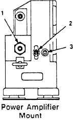
The power amplifier mount is used in the LR/LR radio system. It is bolted to the ve-
hicle. It provides control interface, power and support to the second power amplifier.
1.
2.
3.
Connector J1. Mates with connector on power ampli-
fier. Passes control signals to power amplifier from
mounting base power supply and RT in position B
(page 2-21) .
Switch CB1 . Turns power on and off to power amplifi-
er mount. When set to ON and left there, power is
controlled by CB1 on mounting adapter (page 2-22).
Indicator lamp DS1. Shows when power to power
amplifier mount is on. Lights when CB1 (2) and CB1
on mounting adapter are set to ON. Use dim function
when wearing night-vision goggles. Equipment dam-
age may result if lamp is turned past full bright. Full
dim to full bright is approximately one quarter turn.
2-14


