TM 11-5820-890-10-1
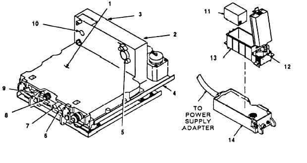
The power supply adapter sets on the single radio mount. For cable connections,
refer to pages 2-24 and 2-26.
1.
2.
3.
4.
5.
6, 7.
8.
9.
10.
11.
12.
13.
14.
Power Supply Adapter: Provides interface and support to RT in single radio
systems using single radio mount.
J3: Used to connect CM.
J4: Used to connect battery (vehicular backup).
Single Radio Mount: Provides power to and holds power supply adapter.
Bolted in vehicle.
J2: Systems connector. Mates with RT systems connector on back of RT.
E1 and E2: Used to connect RCU.
Indicator Lamp and Lens: Shows when power is on. Lights when CB1 is set
to ON. Lens adjusts brightness; turn left (counterclockwise) to make lamp
brighter: turn right (clockwise) to make lamp dimmer. Turn full clockwise
when wearing night-vision goggles. Equipment damage may result if lamp
is turned past full bright. Full bright to full dim is approximately one quarter
turn.
Switch CB1: Turns power on and off to power supply adapter.
Remote/Local Switch S1: Used with AM-1780/VRC. Switch MUST NOT be
set to remote position with power supply adapter set to ON.
Battery: Lithium battery used as backup power for vehicular radio.
Binding Posts: Used to connect RCU.
Battery Box: Holds battery. Mates with battery holder connector for vehicular
radios requiring backup power.
Battery Tray: Used to hold battery and battery box when backup vehicular
radio power is required. Connects to power supply adapter connector J4.
2-15


