TM 11-5820-890-10-3
OPERATION WITH EXTERNAL EQUIPMENT
REMOTE CONTROL DEVICE (C23291GRA39). Do not set the RT FCTN switch to REM.
•
Cabling Diagram. The following diagram shows how to connect the radio to one or two GRA39 Remote Control
Devices.
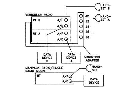
CABLING FOR VOICEIDATA OPERATIONS
TELETYPE (AN/UGC74). Have teletype's internal switches set as follows:
PARITY ODD
CLOCK
+
STATE ICT or KSR
SIGNAL
-
NRZ
REC MODE LO DATA
STOP BITS
-
2
XMIT MODE LO DATA
MODE
-
ASCII
BAUD RATE 1200*
FIGURES
-
(Does not matter with
CLOCK INT
MODE at ASCII.)
*RT can operate with baud rate at 600, or 1200, 2400, 4800, 16000 bits per second (bps). 1200 is preferred. If internal
BAUD RATE switch cannot be set, find out what rate teletype is set to; then set RT DATA rate to match it. If a Y-cable is
provided for connection to a manpack radio, the double is connected to the RT AUD/DATA and AUD/FILL connectors. In
all cases, use J1 on teletype to cable to RT.
NOTE
Refer to the applicable technical bulletins listed in Appendix A when operating external equipment with RT.
4-16