TM 11-5820-890-30-4
CHAPTER 15
MOUNTING BASE, ELECTRICAL EQUIPMENT
MAINTENANCE INSTRUCTIONS
Subject
Principles of Operation
. . . . . . . . . . . . . . . . . . . . . .
Repair Parts, Special Tools, TMDE, and Support Equipment . . . . . . . . . . . . .
Troubleshooting Procedures
. . . . . . . . . .. . . . . . . . . . . . . . .
Maintenance Procedures
. . . . . . . . . . . . . . . . . . . . . . . . . . . .
Preparation for Storage or Shipment . . . . . . . . . . . . . . . . . . . . . . . . . . . . . . . .
MT-6576/VRC
Section
. . . . . . . .
I
. . . . . . .
II
. . . . . . . . . .
Ill
. . . . . . . .
IV
. . . . . . . .
V
Page
15-1
15-2
15-2
15-5
15-22
Section I. PRINCIPLES OF OPERATION
15-1. INTRODUCTION.
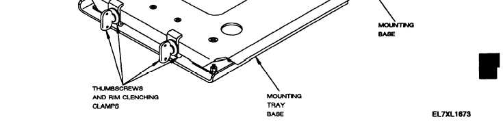
The Mounting Base MT-6576/VRC (SRM mounting base) holds the Power Supply Adapter MX-10662/VRC. It also
provides the electrical interface to the vehicle power. The mounting tray and base are connected by four me-
chanical isolator shock mounts. Six internal electrical leads are used for grounding. The mounting base has two
thumbscrews and rim clenching clamps that hold the power supply adapter in place. There are five connectors
on the electrical connector assembly at the back of the mounting base as shown in figure 15-1 and described in
the following paragraph.
Figure 15-1. SRM Mounting Base.
15-1