TM 11-5820-890-30-4
6-1.
INTRODUCTION. Continued
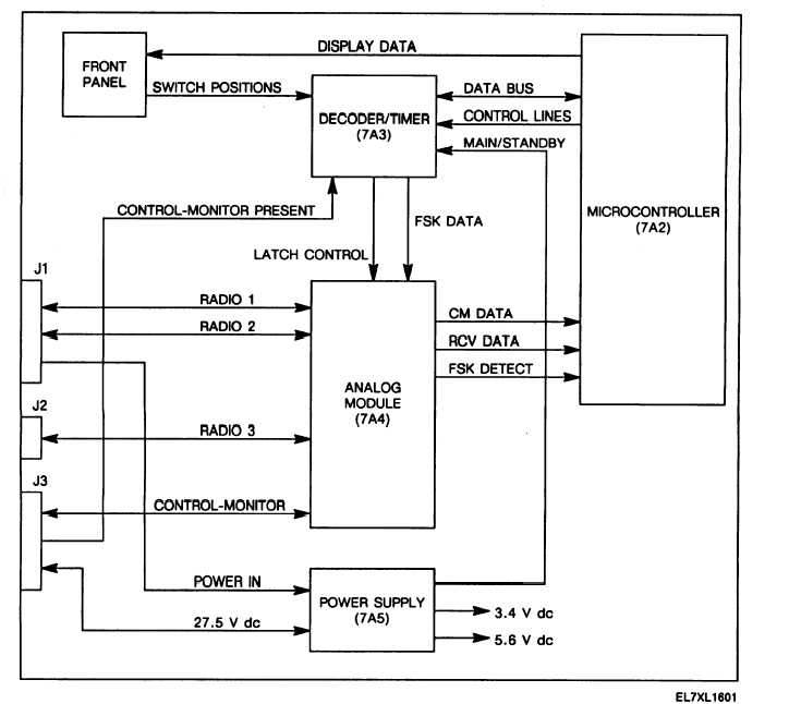
The decoder/timer reads the front panel switch settings. This information is provided to the microcontroller. The
microcontroller responds to received data, generates data to be transmitted, and writes to the front panel
displays. The analog module detects received FSK signals. It routes received FSK and digital data to the
microcontroller. Transmitted data starts with the microcontroller and goes through the decoder/timer and analog
module.
Control-monitor logic levels are as follows:
logic 1 = 3.9 to 6.3 V dc.
logic 0 = -0.7 to 1.7 V dc.
Figure 6-1. Control-Monitor Functional Block Diagram.
6-2

