TM 11-5820-890-30-4
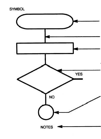
13-12. EXPLANATION OF SYMBOLS AND NOTES.
13-13. TROUBLESHOOTING FLOWCHARTS.
The following charts are included:
Chart
1
2
3
4
5
6
7
8
9
10
11
12
13
14
EXPLANATION
Test Procedure Start: (Rectangle with rounded sides)
Indicates start of the test procedure and contains a brief
description of the symptom of trouble.
Test Procedure Flow Line: (Heavy line) Indicates direction
of the procedure flow.
Test Procedure Instruction: (Rectangle) Provides test
setup or instructions for doing a specific test.
Decision: (Diamond) Indicates that a decision must be
made (YES or NO) in answer to question about the
previous test.
Path taken depends on the answer
(YES or NO).
Connector: (Circle) Directs user to an entry point of
another chart. Contains an entry number that is the same
as entry number of other chart and a sheet number
(Sh. No.) that indicates the number of follow-on pages.
Notes Column: Presents additional information, such
as: more specific instructions about how to do a test,
cautions and warnings that must be observed when doing
a test, and additional information about what to do after
doing a test. Also provides reference to appropriate
circuit diagrams.
Symptom
CB1 trips.
DS1 lamp does not light.
SW 27.5 V dc is absent.
DS1 is lit in RMT.
DS1 does not light in RMT.
No 27 V dc at J1.
No 13 V dc at J1.
Heat sink outputs (6.75 or 200 V dc) are absent.
13 V dc from battery tray is absent.
Troubleshooting remote control circuit.
Troubleshooting continuity between J2 and J5.
Troubleshooting continuity between J1 and J2.
Troubleshooting continuity between J1 and J2.
Troubleshooting continuity between J1 and J2.
13-9


