Home
Download PDF
Order CD-ROM
Order in Print
SECTION III. FFCS AND RIT CREW STATION/RADIO SWITCH SETTING PROCEDURES - TB-11-5830-263-20-140021
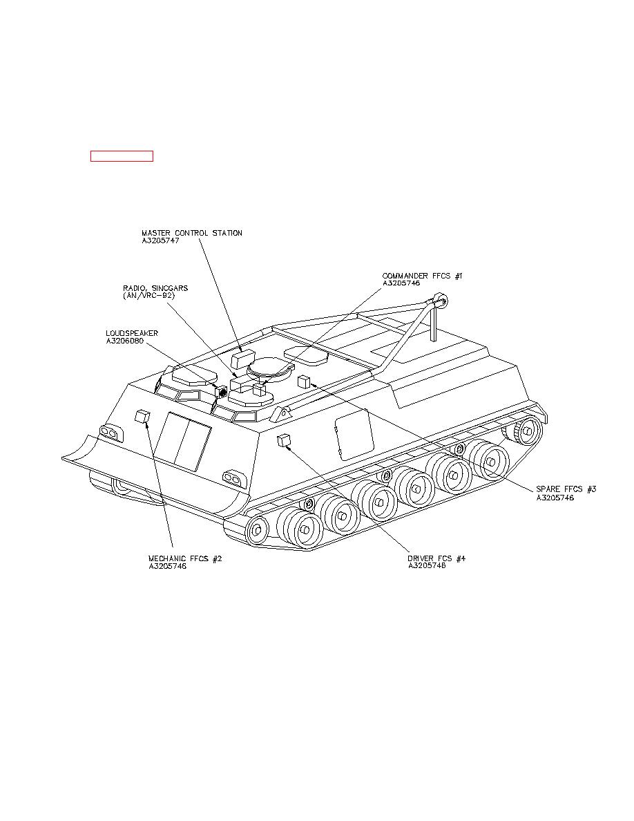
Figure 4-2. System Configuration Diagram - TB-11-5830-263-20-140023
TB-11-5830-263-20-14 Intercommunication Set Vehicular AN/VIC-3(V)14 (NSN 5830-01-452-3568) (EIC: NA) in an M88A2 Recovery Vehicle Manual
Page Navigation
5
6
7
8
9
10
11
12
13
14
15
TB
11-5830-263-20-14
SECTION IV. INSTALLATION
INSTRUCTIONS
4.1
EQUIPMENT
LOCATION
AND
SYSTEM
CONFIGURATION
DIAGRAMS
The
Equipment
Location
and
the
System
Configuration
Diagrams
are
shown
in
Figures
4-1
and
4-2.
Figure
4-1.
Equipment
Location
Diagram
10