TM 11-5820-890-10-3
SECTION II. CONTROL-MONITOR (CM)
ITEM
PAGE
Operator’s Controls, Indicators, and Connectors ............................................................................................................ 4-9
Initial Set-Up and Self-Test ............................................................................................................................................. 4-10
Setting and Changing RT Functions ............................................................................................................................... 4-11
Cabling ............................................................................................................................................................................ 4-12
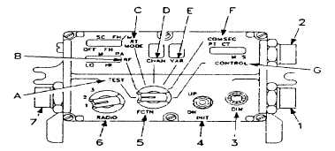
OPERATOR’S CONTROLS, INDICATORS, AND CONNECTORS
Control monitors are used in some vehicles. They enable the remote control of up to two mounting adapters with up to
three RT.
1.
J1 connector. Cabled to main
mounting adapter; RADIO switch
position 1 selects RT in position A of
mounting adapter; position 2 selects
RT in position B.
2.
J2 connector. Cabled to second
mounting adapter (when used);
RADIO switch position 3 selects RT in
position A of second mounting adapt-
er.
3.
DIM control. Adjusts brightness of displays. Turn DIM right (clockwise) to brighten displays; turn it left
(counterclockwise) to dim displays. Turn DIM fully left when you are wearing night-vision goggles.
4.
INIT (initiate) switch. Used with FCTN switch to change functions of RT and CM. Moving INIT to UP makes FCTN
position’s display marker move right; moving INIT to DN (down) makes it move left; function of RT controlled is changed
accordingly. When FCTN is at CHAN, moving INIT to UP or DN makes display number increase or decrease; RT channel
is changed accordingly.
5.
FCTN (function) switch. Used with INIT switch to change functions of RT and CM.
A. TEST. Only used to run CM self-tests. Displays show results. Tests will continue until FCTN is moved out of
TEST.
B. RF. Used to set power output of RT. INIT switch is used for adjusting.
C. RT MODE. Used to set RT mode, including power off. INIT switch is used for adjusting. RT MODE display
shows operating mode.
D. CHAN (channel). Used to select RT channel (including MAN and CUE) and FH hopset. INIT switch is used for
selecting. CHAN displays shows channel selected. 0 on display indicates MAN (manual). C on display indicates CUE.
E. VAR (variable). To be used with future equipment.
F. COMSEC. Will be used to select mode (plain text or cipher text) of future COMSEC equipment. This position has
no effect on current COMSEC units (KY57); VAR display does not show mode to which these units are set.
G. CONTROL. Used to change CM operation from standby (S) to main (M).
When two units are used, only one will be on main (M) at any one time. The other will be on standby (S). The main (M)
unit controls the RT. The INIT switch is used to switch unit from S to M. CONTROL display shows operating condition.
6.
RADIO switch. Selects RT to be controlled. Position 1 is used for the RT in position A (bottom) and position 2 is for
the RT in position B (upper). Position 3 Is for the RT in position A of the second mounting adapter (when used).
7.
J3 connector. Cabled to J3 of second CM (when used).
4-9


