TM 11-5820-890-20-1
1.20.
TROUBLESHOOTING. Continued
Connector. Directs user to an entry point on another sheet in the same chart. Contains an entry
number and sheet number that are the same as the entry number and sheet number found on another
sheet in the same chart.
Notes Column. Presents critical information. States cautions and warnings that must be observed
when doing a test. Has additional data as to what to do or where to go after that step in the testing.
Provides references to appropriate circuit diagrams.
Connector Illustrations. Front views of connectors are placed accordingly to give the maintainer a
visual reference when measuring resistances between pins.
Helpful Hints. When taking measurements, remember that a connector’s pin numbers are mirror
images of those on the connector from which it was removed. Whenever possible, use a chassis ground
instead of a pin ground. This will allow you greater flexibility when taking measurements and can prevent
shorting the equipment.
1.21.
POST-REPAIR USE OF OPERATIONAL CHECK.
When the bad LRU has been found, inspected, and replaced, repeat the Operational Check to ensure that the
system is in fact operational.
1.22.
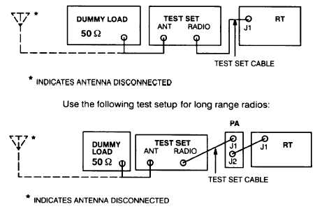
TYPICAL SC TEST SETUP.
For testing RF in SC mode, use the following test setup for short range radios:
1 - 2 2


