TM 11-5820-890-10-3
OPERATOR’S CONTROLS, INDICATORS, AND CONNECTORS
The RCU controls, indicators, and connectors are identical to those on the RT1523 (C)/U with the following exceptions
(refer to the RCU front panel, page 41 ).
CAUTION
LOUDSPEAKER LS685/U IS FOR USE WITH CONTROL, RECEIVERTRANSMITTER C11561(C)/U.
ATTEMPTED USE WITH ANY OTHER EQUIPMENT MAY RESULT IN PERMANENT DAMAGE TO
THAT EQUIPMENT.
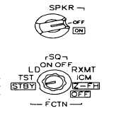
SPKR switch. Controls whether or not loudspeaker LS685/U is ON or OFF. SPKR should be
set to OFF if loudspeaker is not used. Loudspeaker Is disabled when WHSP function is used.
Set to OFF whenever possible to conserve manpack battery life.
FCTN switch. Sets function of RCU. With the exception of the ICM position, the RCU and
radio FCTN switches are identical. ICM position allows operator to communicate with
companion radio without transmitting a signal (COMSEC switch MUST be set to PT ). TST
position tests RCU and radio circuits.
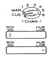
CHAN switch. Selects manual, 1 6, and CUE frequencies. Selects FH hopset.
RCV/SIGNAL (receive signal) display. Lights when companion radio receives signal.
HUB indicator. Only shows HUB life of RCU.
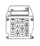
BATT/CALL
(battery/call)
button.
Used to check battery life condition of
manpack RCU and manpack radio.
The first press indicates the battery life
condition of the manpack RCU. The
second press indicates the battery life
condition of the companion manpack
radio (when checking the manpack
radio, the display shows "RT nn"). Also
used to create a ring tone ("CALL" is
displayed on companion radio) at the
companion radio. FCTN switch MUST be
set to ICM to use the call function (radio
may call RCU regardless of RCU FCTN
switch setting).
4-2


