TM 11-5820-890-30-4
13-40. REPLACEMENT OF POWER SUPPLY ADAPTER CHASSIS ASSEMBLY.
Tools:
Flat tip screwdriver
Socket wrench spanner attachment 5/16-inch wrench
Cross tip screwdriver
1 5/16-inch spanner wrench
Long nose pliers
Torque screwdriver
1 1/16-inch socket
Socket wrench
Adjustable wrench
9/16-inch wrench
Soldering kit
Torque wrench
Expendable Supplies:
Silicone compound
Solder
Cotton swabs
Alcohol
References:
Paragraph 13-17 for removal and installation of the heat sink assembly (8A1).
ITEM
ACTION
REMARKS
REMOVAL
a.
Power supply adapter
chassis assembly (1)
b. Two spring pins (2)
c.
Two flat washers (2)
d. Two thumbscrews (3),
bevel washers (4), and
rim clenching clamps (5)
Set on work surface with left side toward
you. See figure 13-8.
Use long nose pliers. Remove and discard
two spring pins (located in cutout on chas-
sis) securing two thumbscrews (3) on the
chassis.
Remove two flat washers from the end of
two thumbscrews and inspect them for
damage. If damaged, obtain replacement.
Remove and inspect two thumbscrews,
bevel washers, and rim clenching clamps for
damage. If damaged, obtain replacement.
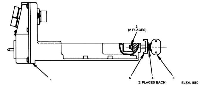
Figure 13-8. Power Supply Adapter Chassis Assembly (Left Side Cutout View)
Without Heat Sink Assembly.
13-64


