TM 11-5820-890-30-4
13-40. REPLACEMENT OF POWER SUPPLY ADAPTER CHASSIS ASSEMBLY. Continued
ITEM
ACTION
REMARKS
REMOVAL Continued
aj.
Four screws, flat
washers, and lock-
washers (12)
ak. Diode CCA (11) wires
al. Diode CCA (11)
am. Power supply adapter
an. 12 captive screws (3)
ao. Rear access cover (2)
Use cross tip screwdriver. Remove and
inspect four screws and flat washers se-
curing the A2 CCA (11) to the chassis.
If damaged, obtain replacement. Discard
Iockwashers.
Tag location of all wires on the diode CCA
(11). Use soldering kit. Desolder each wire
from terminal posts on the A2 CCA (11).
Remove and retain.
Set on work surface with rear toward you.
See figure 13-4.
Use flat tip screwdriver. Fully loosen and
inspect for damage. If damaged, obtain
replacement.
Remove from chassis to allow access to
CR1, CR3 and CR4 diodes, J2 connector,
and the S1 rotary switch, and retain.
See figure 13-11.
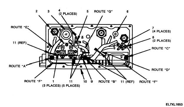
Figure 13-11. Power Supply Adapter Chassis Assembly (Rear View)
Without Rear Access Cover.
13-69


